The Problem
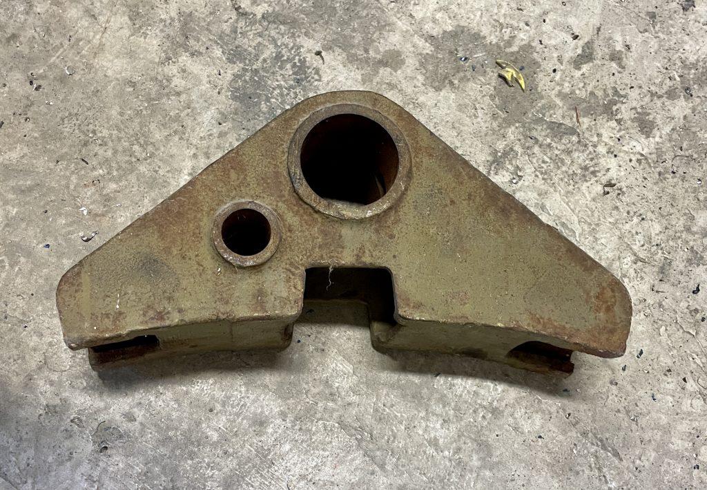
The CC2200 and CC3300-AC are veteran locomotives in CAMRAIL's fleet. Their age means original spare parts are no longer available on the market — creating a maintenance crisis each time a critical component fails. Brake triangles were among the most urgent: worn or broken units could not be replaced through normal procurement channels.
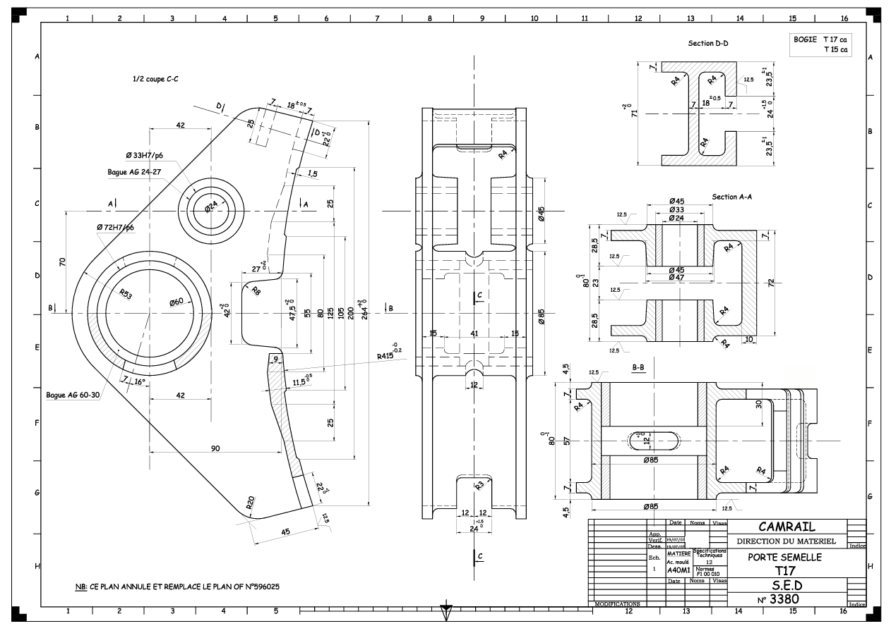
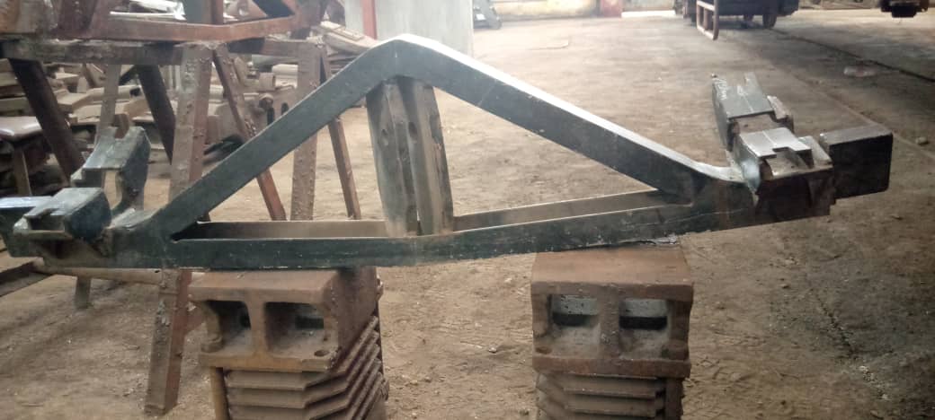
Our team of four engineers was tasked with reproducing two fully functional brake triangles — one for each locomotive type — using locally available materials, tooling, and expertise. The components had to match the original geometry precisely enough to integrate directly into the existing systems, with durability and performance comparable to the imported originals.
An additional constraint was the need to transition from the existing Shielded Metal Arc Welding (SMAW) process to MIG-MAG welding, using newly acquired Lincoln Electric Power MIG 360MP and Fronius TransSteel 2700 units, to meet higher structural standards for railway service.