Compressor Test Bench Optimisation
The Problem
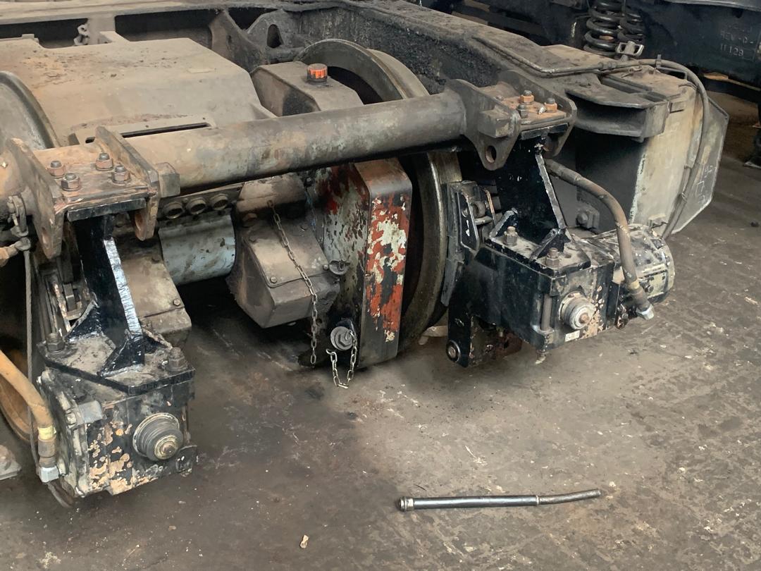
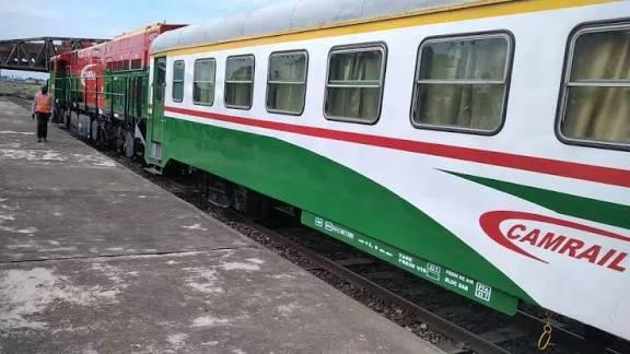
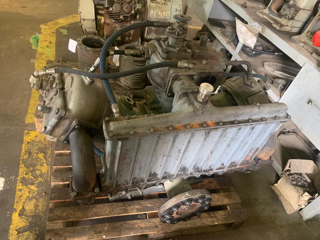
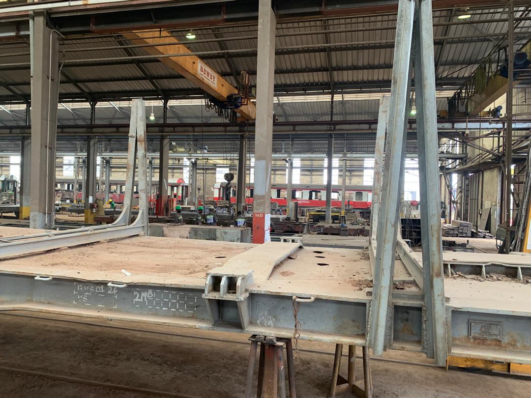
At CAMRAIL, I worked on the optimisation and reconfiguration of mechanical and pneumatic systems on intercity locomotives, focusing on aging models such as the BB1100, CC2200, CC3300, and CC3300 AC, within the context of rolling stock and spare parts shortages. During one critical phase, while preparing locomotives for operational validation, we uncovered subtle incompatibilities in the locomotive compressor test bench — a crucial tool for preventive and corrective maintenance.
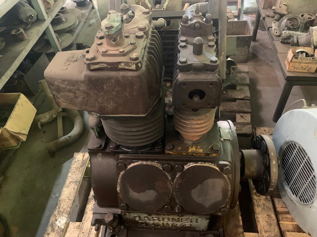
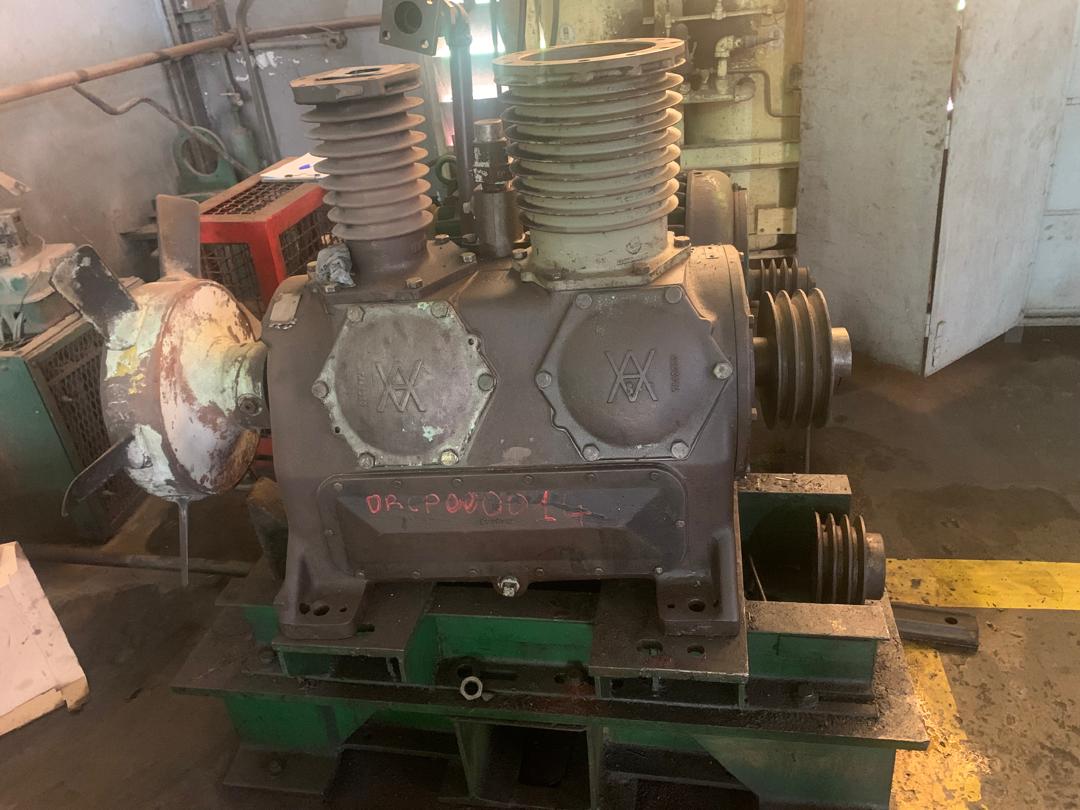
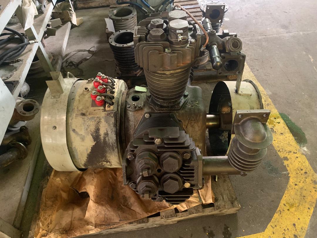
The locomotive compressor ensures air compression and oil circulation, essential for pneumatic systems like braking, control, and auxiliary operations. The existing bench was limited to testing only BB1100 and CC2200 compressors. Other models required fragmented testing in separate locations — water tests in the wash area, hydraulic tests in the garage — introducing time loss, traceability issues, and higher risk of errors.
The Approach
My role was to define and implement a new testing methodology to transform the bench into a versatile, modular, and universal system capable of performing pressurised air, water, and oil tests across multiple compressor types. This involved three parallel workstreams:
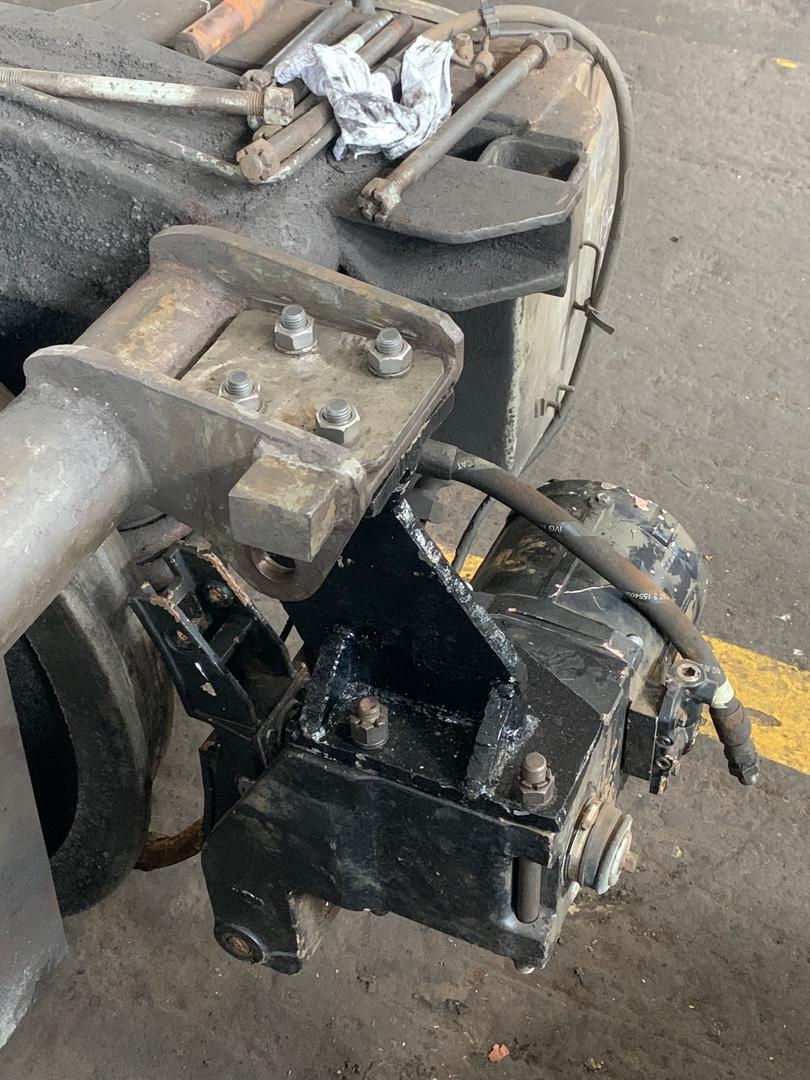
- 3D Modelling and Design — I completed a full 3D model of the bench including the main frame, mounting interfaces, and functional testing zones. The design accommodated compressors of widely varying sizes and weights, from compact BB1100 units to larger CC3300 compressors.
- Low-Cost Modular Frame — The frame was designed for compatibility with multiple compressors, ease of assembly and disassembly, reduced manufacturing costs, and sufficient mechanical rigidity to limit vibrations during testing.
- Functional Analysis and Dynamic Constraints — I analysed vibration characteristics, forces from air and fluid jets, and potential interactions between compressors and the bench structure to prevent instability or mechanical failure during testing.
Additional Scope
Beyond the test bench, I also addressed recurrent radiator overheating in locomotives. This issue arose due to aging fleet components, unavailability of original parts, and the integration of locally designed alternatives that disrupted airflow. My responsibilities included analysing ventilation impacts, proposing pneumatic system modifications, integrating additional radiator ventilation devices, and ensuring the changes did not interfere with other mechanical or pneumatic systems.